
China Zhengzhou Zhongyue Silicon Carbide Electric Heating Element Manufacturer
TEL:+86 13523030448
Email:xy9962@163.com

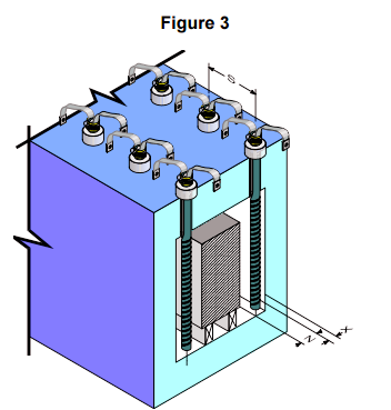
如图3所示,碳化硅电热元件,硅碳棒SiC跨度的炉加热室尺寸可以与SiC元件的热区长度相同。另外,炉加热室尺寸(SiC跨度)可比SiC的有效加热长度小25 mm。在这种情况下,炉壁上必须有45个圆锥形凹口,如图3所示,用于负荷以上的SiC。不同耐火壁和SiC尺寸的推荐端孔直径如表B所示。SiC的放置位置不得相互靠近两个SiC直径,或距离墙壁或其他反射体一个半SiC直径。如果SiC不能在所有方向上均匀地散热,则可能导致局部过热和可能的故障。
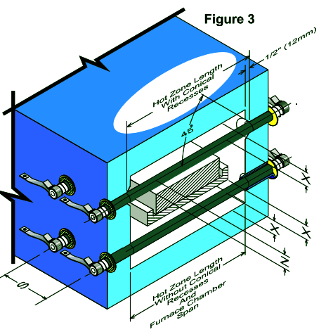
推荐的SiC加热元件间距
X=2×SiC元素直径为最小值,
1.5×SiC元件直径是绝对最小值,需要降低SiC加热元件表面瓦特负荷。
z=s÷1.41静荷载的最小值
Z=S÷1.73最小移动荷载
S=2×SiC元件最小直径
x-是从右侧中心线到任何其他反射面(如耐火墙或产品)的距离。
z-是从SiC加热元件的中心线到移动或静止荷载的距离。
S-是从SiC加热元件中心线到相邻SiC加热元件中心线的距离。
Table B | |||||||||||
Minimum Hole Diameter Based on Refractory Wall Thickness | |||||||||||
Nominal QS Dia. | 100 | 150 | 200 | 300 | 400 | 3 | 5 | 6.5 | 9 | 13.5 | |
mm | Inch | mm | mm | mm | mm | mm | Inch | Inch | Inch | Inch | Inch |
10 | 3/8 | 15 | 15 | 16 | 9/16 | 9/16 | 5/8 | ||||
11 | 7/16 | 16 | 17 | 18 | 20 | 5/8 | 11/16 | 11/16 | 3/4 | ||
13 | 1/2 | 18 | 19 | 20 | 22 | N/A | 11/16 | 3/4 | 3/4 | 13/16 | N/A |
16 | 5/8 | 21 | 22 | 23 | 25 | N/A | 13/16 | 7/8 | 7/8 | 15/16 | N/A |
19 | 3/4 | 25 | 25 | 26 | 28 | N/A | 15/16 | 1 | 1 | 1-1/16 | N/A |
25 | 1 | 31 | 32 | 33 | 35 | 37 | 1-3/16 | 1-3/16 | 1-1/4 | 1-1/4 | 1-7/16 |
32 | 1-1/4 | 38 | 38 | 40 | 42 | 44 | 1-1/2 | 1-1/2 | 1-9/16 | 1-9/16 | 1-11/16 |
35 | 1-3/8 | 41 | 42 | 43 | 45 | 47 | 1-5/8 | 1-5/8 | 1-11/16 | 1-11/16 | 1-11/16 |
38 | 1-1/2 | 44 | 44 | 46 | 48 | 50 | 1-3/4 | 1-3/4 | 1-13/16 | 1-7/8 | 1-15/16 |
44 | 1-3/4 | 51 | 52 | 53 | 55 | 57 | 2 | 2-1/16 | 2-1/16 | 2-1/8 | 2-3/16 |
54 | 2-1/8 | 61 | 62 | 63 | 65 | 67 | 2-3/8 | 2-7/16 | 2-7/16 | 2-1/2 | 2-9/16 |
70 | 2-3/4 | 79 | 79 | 79 | 81 | 83 | 3-1/8 | 3-1/8 | 3-1/8 | 3-3/16 | 3-1/4 |
安装
尽管水平和垂直方向更为常见,但SiC的安装位置没有限制。安装时应格外小心,以确保SiC不会受到张力。应有足够的自由度,允许炉子和SiC独立伸缩。当垂直安装SiC时,必须通过电绝缘支架将其支撑在下端,或从上方使用支撑销将其支撑在具有足够强度以支撑元件重量的隔离板上。SiC端部应超出炉冷面至少3至4英寸或3×元件直径(以较大者为准)。当使用密封的接线盒时,冷端应至少延长元件直径的4-5倍。右舷的加热部分应集中在炉室中,这样加热部分的任何部分都不会延伸到炉墙中。有时,一个1/2英寸(13mm)深的圆锥形或截短圆锥形凹口位于右侧通过的每一面内壁上。这使得热区能够正常辐射,有助于保持窑内温度均匀。
DH&DL SiC元件安装
虽然金刚砂是刚性的和自支撑的,但它的冲击强度相当低,在打开包装和搬运元件时必须小心,以免受到机械冲击。元素应始终由双手支撑。
重要的是要确保元件不受任何方式的限制,并且能够在其支撑孔中自由径向和轴向移动。元件孔必须成一条直线,在安装元件之前,应通过一根与支撑孔直径相同的直棒,直接穿过熔炉检查整个对准情况。
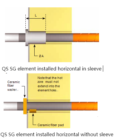
在任何情况下,都不允许元件热区进入元件支撑孔,因为这将导致局部过热和过早失效。特殊引入套管可用于安装Qs-SiC元件的所有直径,这些都是详细的,并且在附件尺寸L中。IST。套管应与炉外、钻孔中的直径相匹配,以确保松配合,且套管不得用水泥固定到位。一般而言,套管的厚度远小于熔炉隔热层的厚度,但间隙孔应钻至热表面,如下所示,以防止元件与衬里之间发生任何接触,因为这可能导致粘附和过早失效。如果不使用套筒,例如在砖砌炉中,则元件可穿过比元件直径大约4–5 mm(1/6–1/5 in)的孔(对于尺寸小于等于20 mm(3/4 in)的元件),而对于尺寸大于25–55 mm(1–2 1/8)的元件,则可穿过比元件直径大约8–10 mm(1/3 in)的孔。in)直径。
如果元件孔或冷端有挥发物冷凝的可能性,或炉衬特别厚,则可能需要更大的孔。
应始终通过在陶瓷材料的小垫上支撑每个冷端来集中元素,以防止元素冷端和引入孔之间的接触。在任何情况下,冷端都不应使用陶瓷纤维或其他绝缘材料包裹,因为这将导致限制和可能的过早失效。
为了防止对终端连接的辐射并将热损失降到最低,可在每个终端上安装一个柔性陶瓷纤维垫圈,并将其放置在熔炉外表面上。
在所有情况下,元件端部应延伸到套管法兰或纤维垫圈外表面以外,距离约为元件直径的2-3倍。
建议使用铝编织线进行终端连接,因为铝编织线不会发生渐进氧化,并且足够平坦和柔软,可以进行良好的连接。
编织物通常使用H型弹簧夹连接,这种弹簧夹易于安装,不需要工具。如果空间有限,可以使用C型夹,这些夹需要安装专用工具。
H和C型夹都依靠弹簧钢保持良好的接触,并且必须保持在250°C以下的温度。对于较高的温度,可使用G型和D型夹钳。
这些螺栓用不锈钢固定螺钉固定在元件上,安装前应在螺纹上涂上高温润滑剂,以防卡住,随后难以拧紧和拆卸。使用24小时后应重新拧紧螺钉。
元件连接必须保持合理的冷却,任何终端防护装置的安装都应通风良好。
如果密封接线盒是必要的,例如在受控气氛炉中,则以下程序
RECOMMENDATIONS FOR CHANGING RR or SE ELEMENTS
1.With the furnace in operation, determine which elements require replacement. This may be accomplished through, visual inspection or by checking the current draw of each element with a clamp-on ammeter.
2.Turn off the electrical power and lock out the electrical disconnect.
3.Remove the clamps and the straps from the ends of those elements which require replacement.
4.Inspect the clamps to be sure that they hold the straps tightly to the element. If the clamp has lost its tension, it should be replaced.
5.Inspect the strap for fraying and oxidation. If the strap is frayed or has an oxidized powder on it, replace it.
6. Remove the two halves of the failed element if broken.
7. Inspect the refractory hole to insure there is no build up or deposition in the opening. If deposits exist, ream the hole or remove them. The hole should be larger than the element diameter (See table B on page 7 of our RR brochure).
8. If element guide sleeves are used, check them for cracks or build-up of condensation residue that could cause elements to be glued into position. Replace the sleeve if damage or condensation has occurred.
9. Check the alignment and straightness of the holes through the refractory. Any binding of the element can cause element breakage during heat up.
10. Slide the new element into the hot furnace quickly enough, so the aluminum at the end is not melted off but not so fast as to cause thermal shock. Avoid hitting the opposite wall with the element. Sometimes an alloy pipe can be used to guide the new element through the heating chamber. The element outside diameter fits inside the alloy pipe inside diameter in this process. Do not force the element into the terminal holes or exert any stress on the element during installation. Page 1
11. Center the element in the furnace chamber by insuring the same amount of element protrudes from each side of the furnace.
12. Lightly pack the open space around the element with bulk ceramic fiber. The bulk fiber should only be packed one half to one inch in from the cold face. After packing, the element should be easily rotated and must be free to expand upon heating. Never cement elements in place. Alternatively, use donut shaped washers made from ceramic fiber felt/blanket, with the ID of the washer made to the same diameter as the element. There is enough “give” in the fiber felt/blanket o be able to work the washers along the terminals for a snug fit. Carefully slide the fiber washers over the ends of the elements, and push up against the furnace casing.
13. Also pack the element inside diameter with bulk ceramic fiber to a depth of one inch, if this has not been done by I Squared R. This will reduce the temperature the straps and clamps will see.
14. Reconnect the straps and install the clamps on the aluminized ends of the element. Be sure the clamps and straps fit tightly to the radius of the element making a good electrical connection. Be sure there is slack in the straps, since the elements will expand and grow in length due to heating.
15. Insure that there is clearance between the clamps and the furnace shell to prevent electrical short circuiting here.
16. Remove the electrical lock and turn the power back on. Visually inspect the elements for proper operation or check the elements for appropriate current draw using a clamp on ammeter.
17. Check the terminal connections to insure no arcing is evident.
18.Turn off the electrical power and lock out the electrical disconnect.
19.Carefully reinstall all guards or shields without hitting the elements
20.Remove the electrical lock and turn the power back on again.
21. Be sure to reset the rotary tap switches to the lowest setting after changing all elements in a furnace zone. This may not be possible if only one or two elements are changed. If rotary tap switches are not available, insure that the elements are operating on the lowest transformer tap to prevent element overloading and premature aging while still being able to maintain the furnace control temperature
RECOMMENDED SE STARBAR SPACING
X - Distance from the centerline of Starbar to any reflecting surface, such as a refractory wall or produc
Z - Distance from the centerline of the Starbar to a moving or stationary load
S - Distance from centerline of the Starbar to the centerline of an adjacent Starbar
X = 2 x Starbar diameter is the minimum,
1.5 x Starbar diameter is the absolute minimum and requires a reduced Starbar surface watt loading
Z = S/1.41 minimum for stationary loads
Z = S/1.73 minimum for moving loads.
S = 2 x Starbar diameters minimum
Installation methods
QS SG element installation Although silicon carbide is rigid and self support- ing, it has a fairly low impact strength, and care must be taken when unpacking and handling the elements so that they are not subjected to mechani- cal shock. Elements should always be supported in both hands.
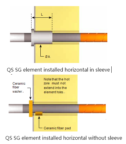
It is important to ensure that the elements are not restricted in any way and are free to move radially, as well as axially, in their support holes. Element holes must be in line, and the hole alignment should be checked by passing a straight bar, of the same diameter as the support holes, right through the furnace, before fitting the elements.
Under no circumstances should the element hot zone be allowed to enter the element support holes as this will lead to localised overheating and premature failure.
Special lead-in sleeves are available for installing all diameters of QS SG and SR elements and these are detailed iand in the Accessories size list. Sleeves should be fitted from the outside of the furnace, in holes bored to a diameter that will ensure a loose fit, and the sleeves should never be cemented into position.
In general, the sleeves will be far shorter than the thickness of the furnace insulation, but the clearance holes should be drilled right through to the hot face, as shown , to prevent any contact between the elements and the lining, as this can lead to adhesion, and premature failure.
If sleeves are not to be used, for example in brick-lined furnaces, then the elements may be fitted through holes about 4 – 5 mm (0.16 – 0.2 in) larger than the element diameter for element sizes up to 19 mm (0.75 in), and about 8 –10 mm
(0.31 – 0.39 in) larger for elements from 25 – 54 mm (1 – 2.13 in) diameter.
Even larger holes may be required where there is a possibility of volatiles condensing in the element holes or on to the cold ends, or where the furnace lining is exceptionally thick.
Elements should always be centralised by supporting each cold end on a small pad of ceramic material, to prevent contact between the element cold ends, and the lead-in holes. Under no cir- cumstances should the cold ends be wrapped with ceramic fiber or other insulation, as this will lead to restriction and possible premature failure.
To prevent radiation on to the terminal connections and minimise heat losses, a flexible ceramic fiber washer may be fitted over each terminal end and positioned so that it rests against the outer face of the furnace .
In all cases, the element ends should extend beyond the sleeve flange, or the outer face of the fiber washer, by a distance of approximately 2 – 3 times the element diameter.
The use of aluminum braid is recommended for making terminal connections as it does not suffer from progressive oxidation and is sufficiently flat and soft to allow a good connection to be made. Braids are normally attached using type HC spring clips, which are easy to install and require no tools.
Where space is restricted, type CC clips may be used, and these require a special tool for installa- tion. Both HC and CC clips rely on spring steel to maintain a good contact, and must be maintained at a temperature below about 250°C (480°F). For higher temperatures, types G or D clamps may be used. These are clamped to the elements using stainless steel set screws, and high temperature lubricant should be applied to the threads before installation, to prevent seizing and later difficulty in tightening and removal. Screws should be re- tightened after 24 hours use.
Element connections must be kept reasonably cool and any terminal guards fitted should be well ventilated. Where sealed terminal boxes are essential, for example in controlled atmosphere furnaces, then the following procedures should be followed:
•Increase the free length of cold end outside the furnace to 4–5 times the element diameter.
•Ensure that the surface area of the terminal covers is sufficient to ensure adequate cooling.
It may be necessary to provide finned covers to increase the surface area.
•Use type D terminal clamps, and larger section connecting braids than normal.
•Introduce a proportion of the process gas via the terminal boxes, to assist in cooling.
•In very severe cases, some kind of forced cooling may be required.
Where QS SG elements are to be installed vertically, a support of electrically insulat- ing, heat-resistant material should be provided below the terminal end.
RECOMMENDATIONS FOR CHANGING RR or SE ELEMENTS
1.With the furnace in operation, determine which elements require replacement. This may be accomplished through, visual inspection or by checking the current draw of each element with a clamp-on ammeter.
2.Turn off the electrical power and lock out the electrical disconnect.
3.Remove the clamps and the straps from the ends of those elements which require replacement.
4.Inspect the clamps to be sure that they hold the straps tightly to the element. If the clamp has lost its tension, it should be replaced.
5.Inspect the strap for fraying and oxidation. If the strap is frayed or has an oxidized powder on it, replace it.
6. Remove the two halves of the failed element if broken.
7. Inspect the refractory hole to insure there is no build up or deposition in the opening. If deposits exist, ream the hole or remove them. The hole should be larger than the element diameter (See table B on page 7 of our RR brochure).
8. If element guide sleeves are used, check them for cracks or build-up of condensation residue that could cause elements to be glued into position. Replace the sleeve if damage or condensation has occurred.
9. Check the alignment and straightness of the holes through the refractory. Any binding of the element can cause element breakage during heat up.
10. Slide the new element into the hot furnace quickly enough, so the aluminum at the end is not melted off but not so fast as to cause thermal shock. Avoid hitting the opposite wall with the element. Sometimes an alloy pipe can be used to guide the new element through the heating chamber. The element outside diameter fits inside the alloy pipe inside diameter in this process. Do not force the element into the terminal holes or exert any stress on the element during installation. Page 1
11. Center the element in the furnace chamber by insuring the same amount of element protrudes from each side of the furnace.
12. Lightly pack the open space around the element with bulk ceramic fiber. The bulk fiber should only be packed one half to one inch in from the cold face. After packing, the element should be easily rotated and must be free to expand upon heating. Never cement elements in place. Alternatively, use donut shaped washers made from ceramic fiber felt/blanket, with the ID of the washer made to the same diameter as the element. There is enough “give” in the fiber felt/blanket o be able to work the washers along the terminals for a snug fit. Carefully slide the fiber washers over the ends of the elements, and push up against the furnace casing.
13. Also pack the element inside diameter with bulk ceramic fiber to a depth of one inch, if this has not been done by I Squared R. This will reduce the temperature the straps and clamps will see.
14. Reconnect the straps and install the clamps on the aluminized ends of the element. Be sure the clamps and straps fit tightly to the radius of the element making a good electrical connection. Be sure there is slack in the straps, since the elements will expand and grow in length due to heating.
15. Insure that there is clearance between the clamps and the furnace shell to prevent electrical short circuiting here.
16. Remove the electrical lock and turn the power back on. Visually inspect the elements for proper operation or check the elements for appropriate current draw using a clamp on ammeter.
17. Check the terminal connections to insure no arcing is evident.
18.Turn off the electrical power and lock out the electrical disconnect.
19.Carefully reinstall all guards or shields without hitting the elements
20.Remove the electrical lock and turn the power back on again.
21. Be sure to reset the rotary tap switches to the lowest setting after changing all elements in a furnace zone. This may not be possible if only one or two elements are changed. If rotary tap switches are not available, insure that the elements are operating on the lowest transformer tap to prevent element overloading and premature aging while still being able to maintain the furnace control temperatur
FURNACE HEATING CHAMBER
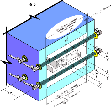
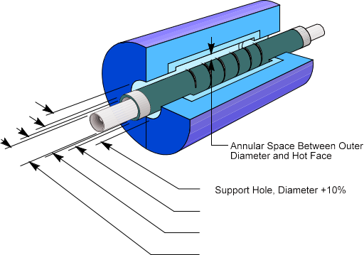
The furnace heated chamber dimension, which the sic heating elements spans, can be the same as the sic elements hot zone as shown The recommended terminal hole diameter is calculated by increasing the sic heating element outer diameter by 20% for sizes up to and including 1-3/8 inch (35mm), and a 10% increase for larger sizes. Table C shows these recommended minimum refractory hole diameters based on the Sic heating element size
Table C | |||
QS Heater | Recommended | ||
MM | Inch | MM | Inch |
13 | 1/2 | 16 | 5/8 |
16 | 5/8 | 19 | 3/4 |
19 | 3/4 | 23 | 7/8 |
22 | 7/8 | 27 | 1-1/16 |
25 | 1 | 30 | 1-3/16 |
32 | 1-1/4 | 39 | 1-1/2 |
35 | 1-3/8 | 42 | 1-5/8 |
38 | 1-1/2 | 42 | 1-11/16 |
44 | 1-3/4 | 49 | 1-15/16 |
54 | 2-1/8 | 60 | 2-3/8 |
70 | 2-3/4 | 77 | 3-1/32 |
Recommended Minnium | |||
44 | 1-3/4 | 49 | 1-15/16 |
50 | 2 | 55 | 2-1/4 |
55 | 2-1/8 | 61 | 2-11/16 |
62 | 2-1/2 | 69 | 2-3/4 |
75 | 3 | 84 | 3-5/16 |
Sic heating element should not be placed closer than two sic elements diameters to each other or one and one half sic elements diameter to a wall or other reflecting body. If the sic elements is not able to dissipate heat energy equally in all directions, it may overheat and possibly fail.
The formula for computing the recommended sic elements spacing to obtain an even temperature gradient on the product being heated is shown in Figure 3, below
RECOMMENDED SER STARBAR SPACING
X = 2 x Starbar diameter is the minimum,
1.5 x Starbar diameter is the absolute minimum and requires a reduced heating elements surface watt loading
Z = S ÷ 1.41 minimum for stationary loads
Z = S ÷ 1.73 minimum for moving loads
S = 2 x Starbar diameters minimum
X - distance from the centerline of Starbar to any reflecting surface, such as a refractory wall or product
Z - distance from the centerline of the Starbar to a moving or stationary load
S - distance from centerline of the Starbar to the centerline of an adjacent Starbar
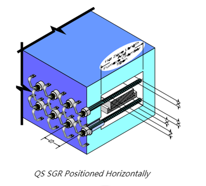
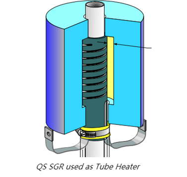
QS SGR element installation
QS SR elements are suitable for both horizontal and vertical installation.
As with QS SG elements, care must be taken when unpacking and handling QS SGR elements, so that they are not subjected to mechanical shock. Elements should always be supported using both hands.
The elements should be installed in an insulating, ceramic sleeve to prevent possible shorting between both cold end halves, because full element voltage exists along the entire length of the terminal.
Precautions must be taken to prevent the terminals from overheating, especially if the elements are operating at the higher end of their temperature range or if the roof lining is relatively thin. In most cases a 25 mm (1 in) thick pad of ceramic fiber fitted below the terminal assembly will be suffi- cient, providing the terminal boxes are adequately ventilated. In more severe cases it may be necessary to mount the elements through a separate support plate, fitted about 75 –100 mm (2.95 – 3.9 in) above the furnace casing, to allow a free flow of air or process gas over the exposed cold ends.
Sleeves must be manufactured from a refractory material capable of withstanding the maximum element temperature (which may be considerably higher than the furnace temperature) and should have a sufficiently high electrical resistivity to prevent conduction between both cold end halves at that temperature. Generally, a high alumina, low iron refractory or vacuum-formed ceramic fiber material will be most suitable.
Sleeves should be fitted from the outside of the furnace, in holes bored to a diameter that will ensure a loose fit, and the sleeves should never be cemented into position. The clearance holes should be drilled right through to the hot face as shown in Fig. 6, and the holes may be flared at the hot face to help prevent any contact between the elements and the lining. Under no circumstances should the element hot zones be allowed to enter the element support holes as this will lead to localised overheating and premature failure.
Elements may also be installed vertically with the terminals at the base and should be located on an electrically insulating, heat resistant support fitted below the terminal end
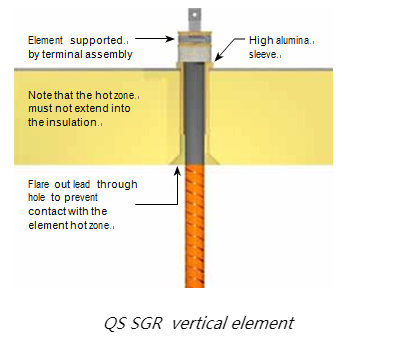
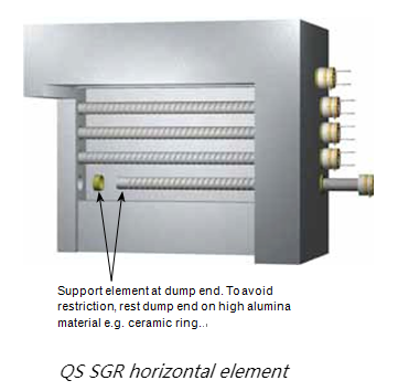
Special precautions are required where SGR elements are to be installed horizon- tally (Fig. 7), especially with long elements where support at both ends is required, and a longer than standard dump end should be specified when or- dering. In this case, the dump end must be support- ed on a hard smooth surface (a high alumina, low iron refractory) in such a way that the element is free to move laterally during heating and cooling.
Although cantilevering of short QS SGR elements may be possible, QS generally recommend that the dump end should always be supported. It is important to ensure that the dump end support is level and co-planer with the ceramic tube supporting the terminal end, otherwise the element may not be fully supported and may fail prematurely
QS SGR elements must always be installed so that the slots in the cold ends are hori- zontally aligned, otherwise tracking across both cold end halves may occur
确保夹钳和炉壳之间有间隙t更换RR或SE元件的建议
1.在熔炉运行的情况下,确定需要更换的元件。这可以通过目视检查或用钳形电流表检查每个元件的电流消耗来实现。
2.关闭电源并锁定电源断开。
3.从需要更换的元件端部拆下夹子和带子。
4.检查夹具,确保其将皮带紧紧固定在元件上。如果卡箍失去张力,应更换。
5.检查皮带是否磨损和氧化。如果皮带磨损或上面有氧化粉末,请更换。
6。如果损坏,拆下故障元件的两半。
7。检查耐火材料孔,确保开口中没有堆积或沉积。如果存在沉积物,应铰孔或清除。孔应大于元件直径。
8。如果使用了元件导套,则检查导套是否有裂缝或是否积聚了可能导致元件粘合到位的冷凝残留物。如果发生损坏或凝结,更换套筒。
9。检查穿过耐火材料的孔的对准度和直线度。在加热过程中,元件的任何结合都会导致元件断裂。
10。将新元件迅速滑入热炉中,使端部的铝不会熔化,但不会很快导致热冲击。避免用元件撞击对面的墙壁。有时可以用合金管引导新元件通过加热室。在这个过程中,元件的外径与合金管的内径相吻合。在安装过程中,不要将元件强行插入端子孔或对元件施加任何应力。
11。通过确保从熔炉两侧伸出的元素数量相同,将元素置于熔炉室的中心。
12。用散装陶瓷纤维轻轻地将元件周围的开放空间包装起来。散装纤维的包装距离冷面只有半到一英寸。包装后,元件应易于旋转,加热后必须能自由膨胀。切勿在适当的位置粘合元件。或者,使用陶瓷纤维毡/毯子制成的环形垫圈,垫圈的ID与元件的直径相同。在纤维毡/毛毯中有足够的“给予”,以便能够沿着终端工作垫圈,使其紧贴。小心地将纤维垫圈滑动到元件端部,并向上推到炉壳上。
13。同样,用大块陶瓷纤维将元件的内径包装到1英寸的深度,如果QS没有这样做,这将降低带子和夹子看到的温度。
14。重新连接皮带,并将卡箍安装到元件的镀铝端。确保卡箍和皮带与元件的半径紧密配合,以实现良好的电气连接。
15.确保皮带松弛,因为加热会使元件膨胀和变长。
o防止电气短路。
16。拆下电气锁并重新打开电源。用钳形电流表目视检查元件是否正常工作或检查元件是否有适当的电流消耗。
17。检查终端连接,确保没有明显的电弧。
18.关闭电源并锁定断开的电源。
19.小心地重新安装所有防护装置或防护罩,不要撞击元件。
20.拆下电气锁,重新打开电源。
21。更换炉区所有元件后,确保将旋转分接开关重置为最低设置。如果只更改了一个或两个元素,这可能是不可能的。如果没有旋转分接开关,确保元件在最低的变压器分接上运行,以防止元件过载和过早老化,同时仍能保持熔炉控制温度。